In the last post, I explained the title of the column comes from the book by Charles Murray The Curmudgeon’s Guide to Getting Ahead. With the Curmudgeon in mind, I have a few more comments to make about our life as Researchers, pushing the leading edge of technology in our industries. In small companies it helps to be a contrarian, to develop novel algorithms in areas overlooked by large research groups or the academic groups funded by them. One such technology that our group started working on a few years ago, nudged by the research group at Saudi Aramco, is Diffraction Imaging (DI). Aramco was looking for a company with a good quality commercial Kichhoff migration, since this particular DI implementation involves modifying a Kirchhoff kernel.
Diffraction Imaging is a high-resolution imaging technology designed to image and identify in very fine detail the small scale fractures in shale and carbonate reservoirs that form areas of increased natural fracture density. Diffraction Imaging provides a separate 3D (stack), 4D (angle gathers) or 5D (angle and azimuth gathers) image of discontinuities, or objects which are small compared to the wavelength of seismic waves such as fault edges, small scale faults, fractured zones, pinch-outs, reef edges, channel edges, salt flanks, reflector unconformities, injectites, fluid fronts, caves and karst, in general any small scattering objects. Our Diffraction Imaging implementation works by eliminating the large amplitude specular reflections from the migrated image and preserving the diffraction amplitudes that can be hundreds of time smaller in amplitude than specular reflections.

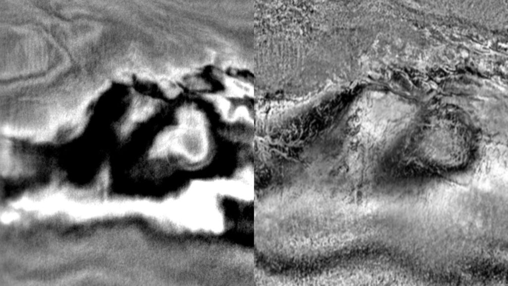
Figure 1: Diffraction imaging depth slice in Eagle Ford. Left PSDM, right DI. Notice the increased resolution of discontinuities.
I was initially reluctant to work on Diffraction Imaging, because to me it sounded as yet another Coherency attribute, similar to negative or positive curvature, and I didn’t think the industry needs yet another Similarity attribute. I found out I was wrong and the Aramco researchers were right after we started to use DI on unconventional shales. First I was wrong because the DI volume is not just an attribute, it is a migration volume with phase and amplitude, and also offset (4D) and azimuth (5D) distribution. The azimuthal distribution of the DI amplitudes gives information about the direction of the stress field. Second, a big surprise to me was the resolution of the faults and fractures that we could see in the DI prestack migrated data. We spent almost a year modeling and DI migrating increasingly smaller discontinuities to understand the limits of resolution of the method. We created a simple model, a few layers with variable velocity and discontinuities of various lengths in the density model. Initially we used finite-difference modeling using a fixed acquisition geometry and fixed output image grid and later we switched to Ray-Born modeling as the length of the discontinuities became meters then centimeters and finite difference modeling on a centimeter grid was too computationally expensive. The conclusion is obvious once I state it, but it took me lots of CPU time to reach it. We could see in the DI migrated image even the centimeter length discontinuities, since there was no noise in the synthetic, the very small diffracted energy from small fractures and discontinuities gets focused in the output grid, independent of the size of the discontinuity. Of course, in real life the noise level in the data impacts the visibility of the small amplitude diffractions, but these were synthetics.
The unconventional shales drilling technology was spearheaded in the early 2000s by small companies with expert drilling engineers, without much focus on seismic imaging, reservoir engineering, or field optimization. The emphasis was on drilling cost and on recovering the drilling cost for each well through individual well production. As larger companies with reservoir characterization and reservoir optimization teams got involved, the emphasis changed from the cost of individual wells to field optimization. It was noticed that wells placed very close using a grid pattern could have very different oil and gas production. The hypothesis was that the structure is very simple and therefore the production should be uniform. In reality the production is not uniform and two wells placed very close by can have very different production.
New high-resolution technologies are needed to define and visualize the structure and the natural fracture distribution and orientation in shale layers. Optimal well placement requires the operator to factor the predominant trend of natural fractures in the selection of the wellbore orientation. Diffraction Imaging is a new approach to image with super-resolution small scale faults, fractures, reflector unconformities, in general any small scattering objects. Typically DI is used as a complement to the structural images produced by reflection imaging. By identifying the areas with increased natural fracture density, the reservoir engineers can design an optimal well placement program that targets the sweet spots, areas with increased production, and minimizes the total number of wells used for a prospective area. Using an optimal number of wells decreases the drilling cost while maximizing production and decreases the environmental impact of developing the field by using less water, using less sand and chemicals pumped in the well and not disturbing the local communities.

Leave a Reply